Glossary
Glossary of Light Microscopy Terms
Binning
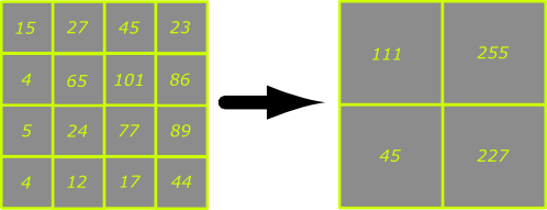
Binning is a process used to increase the sensitivity of a CCD camera by combining the charge from adjacent pixels to boost the signal-to-noise ratio in the image. If we imagine a hypothetical camera (see below) with a chip consisting of 4x4 pixels and we apply a binning factor of 2x then 2x2 arrays of adjacent pixels will be combined together to form an array of 'super pixels' that are four times the area of the originals and contain the combined charges of the adjacent pixels. This improves the signal-to-noise ratio because CCD camera readout noise often obscures low signals. If the readout noise of the hypothetical camera below is 25 grey levels then most of the signals in the image on the left will be indistinguishable from noise. By combining the charges from adjacent pixels the readout noise threshold is easily exceeded in most of the pixels in the image on the right.
Image acquisition is also faster for binned images because the readout time is shorter and the exposure time is usually shorter too. The drawback of using binning is that the resolution is lower because the specimen is now being sampled by fewer pixels. For example, a specimen imaged with the hypothetical camera above in 2x binning mode would be sampled by four large pixels instead of 16 small ones. The images below broadly illustrate the effect of increasing binning factors on resolution. At high binning factors pronounced pixelation is seen in the images when all are magnified to the same dimensions.
What does binning mean? (Andor Technologies)
Gain
Gain is the amplification factor applied to an input signal to adjust the amplitude of the signal output. In confocal imaging using PMTs, an input voltage signal may be multiplied by a positive gain factor to increase the voltage of the signal output and hence the brightness of the image on the monitor. In CCD and CMOS cameras 1X gain is defined as the standard number of photoelectrons assigned per ADU (analogue to digital unit); 2X gain is half the number of photoelectrons assigned per ADU, etc. Since decreasing the gain results in fewer electrons per ADU, the camera is more sensitive to low light levels.
Long Working Distance (LWD) objective lenses
Most biological objective lenses are designed to focus on specimens mounted under a standard #1.5 coverslip, which is about 170 µm thick. Most of these objectives cannot focus through the plastic in the bottom of a standard microtitre plate because their working distances are only a few hundred µm and the bottom of the plate is in the order of 1 mm thick. Long working distance objectives are designed to focus on specimens relatively far away from the front lens and can cope with the thickness of a microtitre plate.
Many LWD objectives have correction collars that can be adjusted for a variety of specimen thicknesses. If a collar has been adjusted for a 1 mm thickness (e.g. the bottom of a plastic dish) it will not focus correctly through a glass coverslip and you will need to adjust the collar to a setting appropriate to a 170 micron thickness.
There is no systematic way of adjusting correction collars. The best way is to set the collar to approximately the correct position before observing your sample, then to focus on the sample, and finally to make fine adjustments to the collar position if necessary. The adjacent picture shows the correction collar of a Leica objective lens when adjusted for a 1 mm sample thickness. The black dot marks the position of the collar and the numbers around the objective barrel indicate the thickness for which the lens will be adjusted. The knurled ring above the dot should be used to rotate the collar. Unfortunately the Leica objectives don't have a mark for the position for a 170 micron coverslip, so the correct position can only be set approximately.
Numerical Aperture (NA)
The numerical aperture is a dimensionless value that characterises the resolution of a lens. It is defined by the following equation:
NA = n sinθ
Where n is the refractive index of the immersion medium and θ is the half-angle of acceptance of the lens.
The higher the NA the higher the resolution of the lens. The NA cannot exceed the refractive index of the immersion medium, so lenses for use in standard immersion oils (n ≈ 1.51) tend to have a maximum NA of 1.4 to 1.45
Links:
Numerical Aperture (Wikipedia)
Point-spread function (PSF)
In fluorescence microscopy a point source of excitation light is focused on the specimen as a diffraction limited spot, which, in the case of a high NA oil objective (NA=1.4 or above) will have a diameter of 200-300 nm, depending on the excitation wavelength. The blurred extended diffraction image is described by a point-spread function, and is a measure of image degradation. It can be determined by taking image stacks through sub-resolution fluorescent beads mounted in the same medium and emitting at a similar wavelength as fluorophores as the specimen. Alternatively, it can be calculated theoretically using the microscope control software or commercial algorithms.
Working Distance (WD)
The working distance is the distance from the front of the lens to the nearest surface of the coverslip when the specimen is in sharp focus. For objective lenses designed for use without a coverslip the surface of the culture vessel or specimen in used.
Links:

