Olympus FV1200 Quick Start Guide
FV1200 Software - Quick Guide
This PDF Quick Guide shows the FV10-ASW 4.2 software user interface and summarises the key features required for basic image acquisition. It prints out onto an A4 sheet for handy reference.
Starting up the microscope
- Turn on the Fluorescent Lamp wall socket switch to the left of the air table.
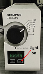
- Press the ON/OFF button on the front of the U-HGLGPS fluorescent lamp beneath the air table. It is on when the blue Burner Status LED comes on.
- Check that the Computer and Monitor socket switches are switched on at the wall and start the computer up by pressing the main power button
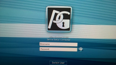
- The pGina authentication screen takes the place of the normal Windows login. Wait until its service status changes to Connected and then login with your Agendo booking system credentials.
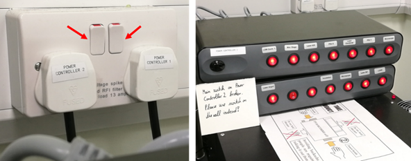
- Switch on the wall sockets labelled Power Controller 1 and Power Controller 2. These will power up most of the microscope devices. Do not use any of the switches on the power controllers themselves; these should always remain switched on.
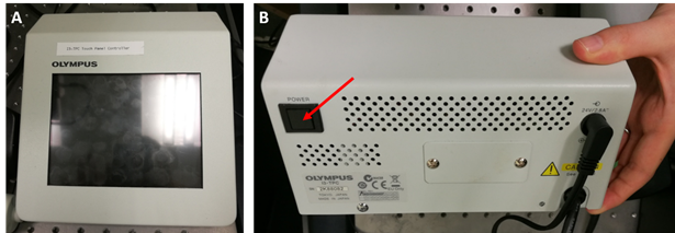
- Turn on the I3-TPC Touch Panel Controller by pressing the power button on its back (see arrow in panel B below).
- Press Start Operation on the I3-TPC touch screen.
- Most of the laser power packs are on the shelf above the microscope. The main power switches of the lasers are always in the ON position.
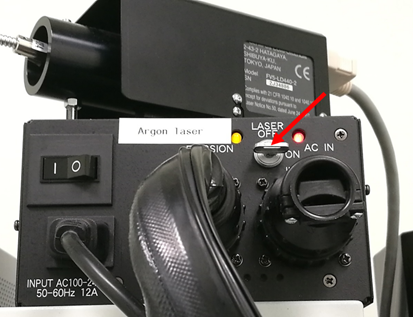
- Turn the Argon laser key to ON.
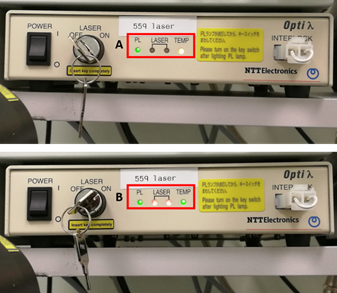
- The 559 laser Opti λ power pack receives mains power when Power Controllers 1 and 2 are turned on, at which point the TEMP LED will start flashing (A below). The LED will continue to flash for 5 - 10 min. Once it stops, turn the LASER key to ON and wait for a few minutes for the two red LEDs labeled LASER to stop flashing (B below). Do not open the confocal microscope software until these stop flashing.
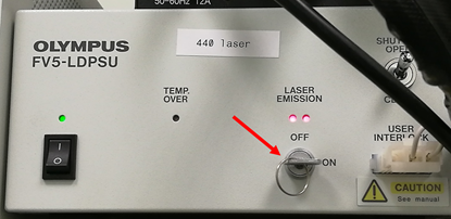
- If you would like to use the 440 nm laser to excite CFP and other cyan dyes you will need to turn on the FV5-LDPSU controller key, otherwise this does not have to be turned on.
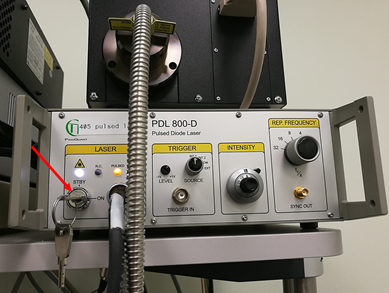
- If you need to use the pulsed PicoQuant 405 nm laser for ablation experiments turn the key on the PDL 800-D controller on the shelf from STBY to ON, otherwise this can stay in the STBY position.
- Double-click the FV10-ASW 4.2 icon on the Desktop to open the software. Select the Guest user ID in the 'Welcome to FV10-ASW' dialog and click OK. There is no password for this account.
- The software will take some time to start during which 'Hardware Initializing…' will be displayed on the computer screen and the touch panel controller will say 'Connected software is sending information to this device'.
- Allow the lasers at least 30 min to warm up before you start imaging. You are now ready to put a specimen on the microscope and set up your image acquisition.
Putting your specimen on the microscope and getting it into focus
- Insert a stage adaptor for your specimen. There are adaptors for slides and a Tokai-Hit stage-top incubation system for 35 mm dishes and chambered cover-slips
- Select an objective lens from the tabs at top of the touch panel screen or from the drop-down menu in Acquisition Setting in the software. When you click on an objective it will automatically be rotated into position.
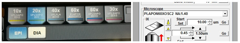
- Choose the correct immersion oil and put a small drop on the lens. There are three immersion oil bottles available: A green one with silicone immersion oil for the 30x and 60x silicone oil lenses; a blue bottle of Type F for use with standard oil immersion lenses (20x, 40x and 60x); and a bottle of Zeiss Immersol W for use only with the 60x water immersion lens. Don't put oil on the wrong lens; refer to the objective lens technical specs if you are unsure.
- Put your sample into the stage adapter (if you are using a microscope slide make sure that the glass coverslip is facing downwards, as it is an inverted microscope). Pull the transmitted light arm back down. When the transmitted light arm is pushed back a safety interlock will prevent the lasers from working, so it must be pulled into place before scanning.
- To focus on your sample press the EPI or DIA buttons on the touch pad for fluorescence or transmitted light respectively (see objective lens figure above).
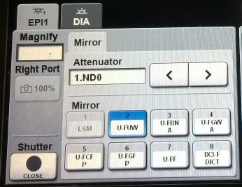
- If you want to focus using transmitted light illumination, press the DIA button and select the DIA tab on the touch panel. This will give you access to controls for the transmitted light components and shutter. It is important that you select the DIA tab; otherwise when you press the shutter button in the bottom left corner you will open and close the fluorescence shutter. In the DIA tab you can control the lamp voltage; iris aperture size; and in the Elements tab, which DIC prisms are in the light path. Setting the light path up for DIC is covered in a separate document.
- For epifluorescence illumination press the EPI tab and select a fluorescence filter cube from the Mirror tab. Briefly, 2 (U-FUW is for blue fluorescence), 3 (U-FBNA is for green fluorescence) and 4 (U-FGWA is for red fluorescence), but see the fluorescence filter cube specifications for a full description of the available filters. Make sure that the fluorescence shutter (bottom left corner on touch panel controller) is open.
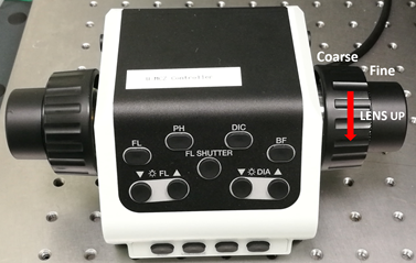
- Use the U-MCZ controller focus wheel to focus on your specimen, rotating the focus wheel anticlockwise to raise the objective towards the sample.
Adjusting settings and acquiring images
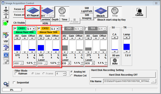
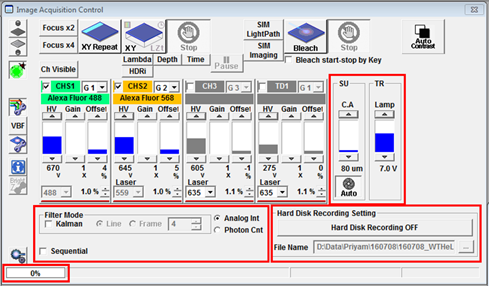
- The easiest way to create suitable laser and detector settings in the FV10-ASW software is by using the Dye List. This can be accessed by clicking the on the Dye List icon located on the right hand side of the Image Acquisition Control panel.

In the Dye List menu (shown below) drag the dyes you would like to use into the Selected Dyes box or double-click to select them. If you want to remove any dyes you can drag them out of the list individually or click clear all to remove all dyes and start over. Click Apply and the lightpath for the selected dye combination will be configured automatically (includes activation of lasers and selection of detectors and filters)
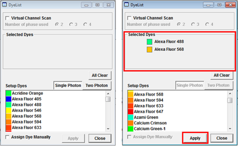
You cannot select more than three dyes at a time using the Dye List and certain dye combinations are not possible because the dichroic mirror combinations do not allow them. If you would like to image such a forbidden dye combination this can be achieved by using the Virtual Channels tool. How to set this up is described in the section USING VIRTUAL CHANNELS TO ACQUIRE MULTICHANNEL CONFOCAL IMAGES.
- The combination of detectors activated in the Image Acquisition Control window (CHS1, CHS2, CH3, etc.) depends on the dyes you chose. The lasers you need for fluorescence excitation will be automatically ticked in the Acquisition Setting menu. Click the XY Repeat button to open a Live View window to preview your specimen. You can stop the scan by clicking RepeatStop. Clicking the Focus x2 or Focus x4 button will also initiate a live scan. These are high-speed scans that have a lower resolution but you can use them to focus easily on your specimen and adjust laser power, gain etc.
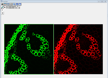
- The Live View below shows a green and red fluorescenct section of plant root. The signal in both channels is saturated, meaning that the light is too bright and the detector is measuring maximum signal in large parts of the image. It would be impossible to quantify fluorescence within the saturated regions because the intensity value is off the scale. In such a case it is necessary to adjust the imaging settings to reduce the intensity to a measurable level.
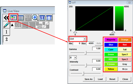
- Before adjusting the settings it can be useful to change the image colour look-up table (LUT) to Hi-Lo. This is a greyscale LUT with the brightest and dimmest pixel values (usually 255 and 0) coloured red and blue, respectively. Click the LUT (Look Up Table) button in the Live View window to open the LUT panel. Select the channel for which you would like to change the LUT, i.e. CH1, then select a Hi-Lo on the right. There is a choice of other LUTs if you want to change the appearance of your image later on.
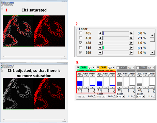
- Increasing the laser power (2 below) will increase the fluorescence emitted by your specimen but will also increase the bleach rate and phototoxicity. Also, the intensity will no longer increase if all the fluorophores in your specimen are already in the excited state. The detector voltage HV (3 below) increases or decreases the brightness by changing the amplification of the signal. This won't result in bleaching but it does amplify the photon noise to the same degree as the signal and also adds some multiplicative noise. Gain is a 'digital gain' that simply applies a multiplication factor to the digital value of all the pixels. Offset changes the black level of the image. Increasing the offset will make the background darker by setting more pixel values at the lower end of the scale to zero. Make these adjustments for all channels that you would like to image, then change the LUT to whatever colour you want.
In the Acquisition Setting panel you can change the Mode from Oneway (unidirectional) to Roundtrip (bidirectional) scanning. In most cases it is better to use Oneway rather than Roundtrip scan mode on this machine. Roundtrip mode can be used for high speed imaging if some adjustments are made to align the two scan directions. You can acquire images with special formats such as Lines, Points or Rectangles by selecting one of the ROI buttons to the right of Mode. In practice, most users will not want to change this. The pixel dwell time can be adjusted by dragging the slider between <<Fast and Slow>> and setting it to the desired scan speed (e.g. 2 µs/pixel). Decreasing the pixel dwell time allows faster scanning but with a lower signal to noise ratio.
The pixel dwell times can be set to different values for 2x, 4x and XY Repeat, so watch out for that. You can adjust the dwell time so it is the same for all these conditions. The dwell time for XY Repeat will be the one used for any subsequent image acquisitions.
In the Size section the frame format (number of pixels that will be imaged) can be changed by adjusting the slider position. In the Area section the field that is being imaged can be changed or rotated around. You can also zoom using the slider on the right to look at a smaller field of view.
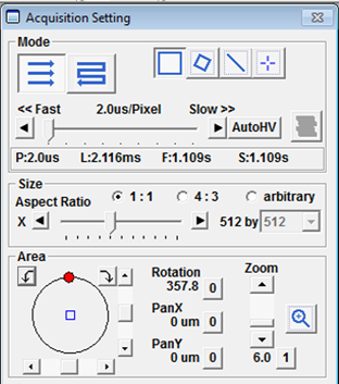
In the Image Acquisition Control window the SU slider can be used to change the confocal pinhole size. Usually it is set to Auto, so it will be the optimal size to reject out-of-focus light without losing too much signal. It can be opened wider to increase signal at the expense of axial resolution. The Kalman checkbox in Filter Mode will turn on Line or Frame averaging to improve the signal to noise ratio in images.
Acquiring and saving images
- When all imaging parameters are set up press the XY button to start the image acquisition.
- When the image acquisition has finished a new window with the recorded image file will open. To save the image highlight it, go to file Save as…, enter a filename and click save. Files are best saved as .oif or .oib, which are Olympus’ own file formats containing all acquisition metadata. You should save all data on the PC’s D: drive when acquiring and later copy them to a safe location such as your project folder on the UCL Active Directory. Instructions how to connect to your project folder can be found here.
To the right of Filter Mode you can turn on Hard Disk Recording (equivalent to Auto Save in other softwares) by pressing the button and selecting a folder to save the data in. This should be used for any acquisition where the data generated is likely to exceed the maximum capacity allowed by the acquisition software (e.g. overnight time series or large tiled 3D images). You will have to define a file format in which to save the data.
OIB is the newer of the Olympus image file formats. In contrast to OIF, in which images are stored as a folder of individual TIFFs with an OIF index file, OIB stores all images and metadata in a single file. If you intend to use Volocity software for 3D reconstruction, deconvolution or measurement then you will need to use OIF because Volocity cannot read the OIB format.
Simultaneous and sequential acquisition
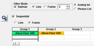
Check the Sequential checkbox to make sure that the different colour channels in your images are acquired sequentially rather than simultaneously. Sequential imaging is slower than simultaneous but reduces crosstalk when using fluorophores with overlapping excitation or emission spectra.
You can define which channels are scanned simultaneously and which are scanned sequentially by dragging them into different Groups. In the example below Alexa Fluor 488 and Alexa Fluor 568 are in different groups and will be scanned sequentially. If I was also imaging Alexa Fluor 647 I could have that in a third group or I could shorten the scan time by dragging it into Group 1 to be scanned simultaneously with Alexa Fluor 488. It is possible to scan a Live View in sequential mode but when Frame sequential is selected only the currently selected channel will be refreshed.
Z series
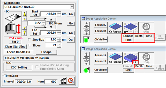
A Z-stack can be configured in the Acquisition Settings panel. You have the option to reset the current focus position to zero, which you can do by pressing Set 0 (but see the warning below). Focus on the plane where you would like to start the Z-stack and press Set under Start, then focus on the last plane of the stack and press Set under End.
Warning
If you want to reset the focus position to zero, do it before you set the Start and End positions, otherwise the Z series will be many microns out of focus.
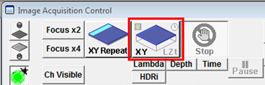
Set a Step size in μm by typing in a value or press Op. for the microscope to set the optimal step size for the objective lens currently being used. If the Z-stack menu is hidden just double-click on Microscope to display it. Click Depth beneath the XY button in Image Acquisition Control. If Depth is not clicked then only a single XY plane (no Z) will be captured when the scan starts. The Lambda, Time, etc. buttons should be activated for spectral scans, time series and other combinations.
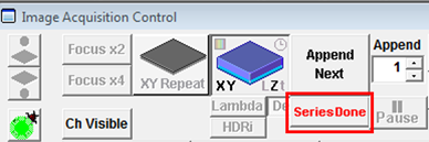
- When the Z series is finished you must press Series Done (below) to open a window displaying the Z-stack, which you can then save. Alternatively you can press Append Next to acquire another Z-stack and append it to the previous one, but this is not likely to be a common practice.
Time series
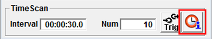
Time series can be configured at the bottom of the Acquisition Setting panel. Under TimeScan enter the Interval time in 00 (h):00 (min):00 (s).0 (ms). In the Num (number) enter how often you would like this interval to be repeated. Make sure the interval is not shorter than the time it actually takes to acquire the image. Click on the Info button (see picture below) to get an estimate of how long a single scan will take.
- Make sure Time is clicked under the XY button in the Image Acquisition Control panel before you start acquiring a time-series. When the acquisition of the time series has finished press the Series Done button to obtain the final data set in a new window and save it or press Append Next to acquire another time series and append it to the previous one.
- It is also possible to acquire data sets containing a combination of a Z- and temporal information. For this select Depth and Time beneath the XY-Start button.
For more advanced experiments such as multichannel acquisitions you can have a look at the sections USING VIRTUAL CHANNELS TO ACQUIRE MULTICHANNEL CONFOCAL IMAGES or MULTI-AREA TIME-LAPSE IMAGING.
Shutting down the microscope
- Remove your sample from the microscope stage and clean all objectives you have been using carefully with lens cleaning tissue.
- If someone is going to use the microscope later in the day (check microscope booking system), save your files, quit the FV10-ASW 4.2 acquisition software and logout of Windows.
- If you are the last person using the microscope that day, shut the complete system down.
- Save your files and close down the FV10-ASW 4.2 acquisition software.
- Shut down the PC.
- Switch of the fluorescence lamp using the ON/OFF button and wait until the countdown on the front LED display has gone to 0 before turning off the wall switch. The lamp needs to cool down for about 10 min.
- Turn all laser keys to the OFF position
- Allow the argon laser to cool for 30 minutes and then switch off the Power Controller 1 and Power Controller 2 wall sockets.