STED imaging guide
Introductory guide to STED super-resolution imaging using the Leica Microsystems TCS SP8 STED 3X.
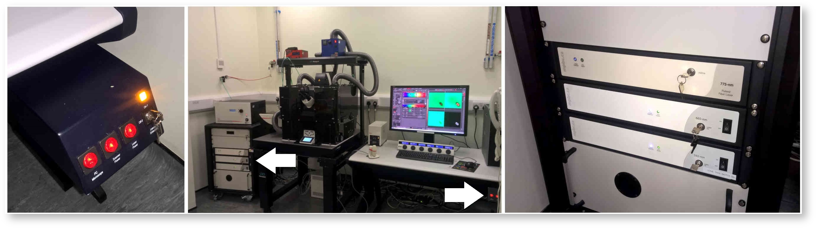
Microscope start-up
Switch on the PC Microscope, Scanner Power and Laser Power buttons and turn the Laser Emission key from Off to On. Wait for the computer to boot up, login to the account and then turn on the depletion lasers. These are on the power supply to the left of the microscope, labelled 775-nm, 660-nm and 592-nm. The switches should always be left in the on position, but the keys will need to be turned one quarter-turn clockwise to the Laser On position.
Software start-up
Double-click the LASX icon on the computer desktop. When the splash screen appears, change the STED button from Off to On. Then click OK.
![]()
Initialise the stage when prompted if you need to use the Tile Scan or Mark & Find modes, but before you do so make sure there is no sample on the microscope and that the condenser is raised high enough so the stage doesn’t hit it as it moves.
Once the software has started up the lasers need activating. Click the Configuration button near the top left of the LASX user interface, then click the Laser Config button on the left-hand side of the Configuration window. Turn on the white light laser (WLL) and the depletion lasers STED 592, STED 660 and STED 775. Turn the three depletion lasers up to 100%. The WLL should automatically be at right power (70%). You only need to switch on the 405 Diode if you want to image DAPI, Hoechst or other blue dyes.
Activate STED and Align Beams
Click on the Acquire button at the top to return to the acquisition controls. STED is only possible using the specially corrected 100x HC PL APO CS2 oil lens, so select this lens from the Objective drop-down menu. Once this lens is in position you will be able to click the Activate STED button in the top-right of the controls. The button will remain greyed-out until the 100x lens is in position. Once the Activate STED button is pressed the controls for the STED 3D and STED laser powers will become visible.
When you activate STED, you may receive a prompt warning you to carry out a beam alignment. You should do this whether or not you receive a prompt because in my experience the lasers can become badly misaligned over time and aligning the beams corrects that.
Go back into the Configuration window and click the STED button on the left. Click the Align Beams button. The beam alignment procedure automatically runs for a minute or two using a test target in the scan head. It is not uncommon (likely even) that the alignment will fail initially. If this happens, just click Align Beams again. You may need to do this a few times, but if it continues to fail after four or five tries then contact SuRF staff members to report the problem.
Acquisition parameters for STED
The following instructions will give an example of how to set up the parameters for a sample where nuclear pore protein (Nup) is labelled with the dye Star 635P. This dye is excited at 635 nm or thereabouts and STED is achieved using the 775 nm laser for depletion.
Lasers
The excitation laser used for STED and for most other imaging on the machine is the WLL. This is a tuneable super-continuum laser that can be tuned to any wavelength from 470 nm to 670 nm. It also pulses at 80 MHz (every 12.5 ns), which is an essential feature for STED.
For Star 635P you need the WLL excitation line at 633 nm and not 635 nm. This is because there are notch filters in the Fluorifer disc that supress reflections at common laser wavelengths and 633 nm is one of these wavelengths. The notch filters prevent the detection of reflections when imaging at or near the surface of coverslips. Unless the settings have already been configured there will be a laser line set at 470 nm as standard. You can either drag that up to 633 nm or type in 633 instead of 470 and press return. Set the laser power to 11%, which corresponds to (very approximately) 100 μW. Turn the STED1 laser button ON and drag the 775 slider up to 50%.
Hybrid Detectors and Gating
You need to use the Hybrid Detectors (HyD) for STED rather than the photomultiplier tubes (PMT). The HyDs are more sensitive and they are fast enough to allow gating of the signal. Gating prevents the detection of photons during and immediately after the excitation pulse, which improves the resolution and reduces the need to use high depletion laser powers.
Switch the button for HyD4 from OFF to ON. I have suggested using HyD4 because it makes it easier to use HyD2 for another shorter wavelength channel if you want to do two-colour STED. You could also use HyD5. I usually set the detector gain to around 100 for this sample, but this is arbitrary and depends on how bright your sample is. Tick the Gating box and set the lower and upper gates to 0.5 ns and 6 ns respectively. Gating is only required for STED imaging, so you have the option to untick the box when doing confocal imaging.
Emission wavelengths
The STED has a spectrophotometer-based SP filter system that allows the user to resize the emission wavelength range by dragging sliders. The wavelength ranges for detectors that are ON are highlighted in the graphic representing the visible spectrum. Drag the upper and lower sliders for HyD4 or whatever detector you are using to 646 and 729. This will establish an adequate detection range for Star 635P emission and will not overlap with either the excitation (633 nm) or depletion (775 nm) lines, which would saturate the detector. The detection range is arbitrary and you may choose to make it bigger, but you must avoid overlap with any active lasers and you should try to avoid emission crosstalk if you sample is labelled with multiple dyes.
Live confocal preview scan
Put your sample on the microscope and get it into focus if you haven’t done so already. Once the sample is in focus it’s best to adjust the acquisition settings to get a good confocal preview of your specimen before making final adjustments the STED settings. The easiest way to do this is to turn the STED1 laser button OFF and then click Live. You can also untick Gating to get a brighter signal, but I don’t usually bother because leaving the gating on will give you a better impression of the final brightness of the STED image.
Laser power and gain
Adjust the laser power and gain to get a bright image. I press the M button in the toolbar to the left of the live image, so the live image automatically adjusts the contrast as it scans (the button becomes an A in auto-contrast mode). Note that the image contrast adjusts after each scan, so if your scan is slow you may have to wait a bit to see a change. I try to get the brightest confocal pixels to over 200 grey levels. This is in the default 8-bit range (255 grey levels total). The value will be different in 12-bit or 16-bit ranges.
Optimise Zoom and Scan Format for STED
Use the Zoom Factor and Scan Format to optimise the pixel size and hence the (lateral) resolution. I normally adjust the pixel size to around 70 nm for confocal microscopy, but the pixel size must be smaller for STED. The easiest way to set the pixel size for STED is to make sure the STED1 laser button is ON and Gating is ticked and then click the button that optimises the scan format. This changes the scan format for a given zoom factor, so it is correct for STED. Remember to switch off the STED1 button if you want to capture a confocal image.
Capture images and stacks
Before capturing an image it’s best to specify a Line Average to reduce noise. I usually set it to 3 for this specimen. Press Capture Image to acquire a single scan or Start to acquire a sequence (e.g. XYZ if you’ve set that up).
To save the image, click on the Open Projects tab and save the project (the default format is LIF). You can rename the image by right-clicking it in the project. You can create a new project by clicking the New Project button in the toolbar and you can drag existing images into that while holding down the Shift key. Dragging the image without holding down Shift will copy it to the new project rather than moving it.
To capture a STED image of the same field, turn the STED1 laser button to ON (not forgetting to tick Gating if that isn’t already active). Leave Line Average on 3 but set Frame Accumulation to 3 also. This will accumulate the signal from three scans, which is necessary because fewer photons are captured per pixel in STED than in confocal.
Capture Image will only capture a single plane. If you want to capture a stack, then click on the focus plane graphic in the Z-Stack control and use the track wheel of the mouse to move the Z-Galvo focus up and down. Click the Begin and End buttons to set begin and end planes for your stack. The trash button scraps any previous Begin and End points and the centre button next to it moves the Z-Galvo to the centre of the range. If the desired STED parameters are active (e.g. STED1 button) then the System Optimized button will set the Z step to the optimal for STED. If the STED parameters are inactive it will optimise the step for confocal. You can make manual adjustments to the step size if you click the Z-Step Size or Number of Steps radio buttons.
You can capture a Z series in either confocal or STED mode by clicking the Start button. Note that at lower zoom settings STED images can have very large scan formats because of the small pixel size. When this is combined with the line averages and frame accumulations it means that a single plane can take a long time to scan and a stack will take correspondingly long. To mitigate this, you can do such things as zoom in to an area of interest, change the scan format to a non-square ‘slot’ format or reduce the number of slices in the Z series. Series can be saved and handled the same way as images in the Projects tab.
3D STED
Conventionally STED has been achieved using a doughnut-shaped laser beam to deplete fluorescence in all but the very centre minimum of the doughnut. This beam does not increase resolution in the axial (Z) dimension and so is referred to as 2D STED in the Leica system. 2D STED is the default mode and gives the best lateral resolution increase but more recently a separate light path with a 3D depletion pattern has been introduced. The superimposition of the two depletion patterns improves the resolution in Z leading to 3D STED. Moving the STED 3D slider from 0 to 100% increases the percentage of the 3D depletion pattern relative to the 2D pattern, increasing the Z resolution while decreasing the lateral resolution. The sketch of estimated effective PSF will give you an impression of the PSF shape at different percentages. As the percentage increases the contribution of lobes above and below the plane of focus increases, so the 3D STED images benefit from deconvolution using a 3D STED PSF.
Both 2D and 3D STED images benefit from deconvolution because the signal to noise ratio (SNR) in STED images tends to be low. Deconvolution improves SNR as well as improving the resolution still further. Images and series can be directly exported from LASX into the SVI Huygens Professional software by right clicking the image in the Project tab and selecting Export to Huygens Professional. Deconvolved data can be exported from Huygens back into LASX. Alternatively, saved LIF files can be deconvolved in Huygens either on the acquisition PC or on an offline analysis station.
Multi-colour STED
Multi-colour STED is possible using one or more of the depletion lasers. If you need to examine the colocalization of fluorescently labelled structures, it is preferable to use dyes that can be depleted using the same STED laser. For example, Alexa 594 and Star 635P are a good combination to use with the 775 nm depletion laser. Different STED lasers can be used but they have different dichroic mirrors for combining them with the excitation path and changing those mirrors could cause a small shift in the colour registration in the final image, necessitating the use of fiducial markers. A disadvantage of using dyes that are depleted using the same STED laser is that they tend to emit in similar regions of the spectrum and therefore suffer from crosstalk. Therefore, sequential imaging must always be used for multi-channel STED and the emission windows must be carefully optimised to avoid crosstalk and reflection from the excitation and STED lasers.
Another very important point is that depletion lasers will photobleach dyes whose excitation spectra overlap with the wavelength of the beam. What this means in practice is that for multi-channel imaging using more than one depletion laser you must set up the first sequential channel for the longest wavelength dye and capture shorter wavelengths with each subsequent sequential channel. For example, you could set up a three-colour imaging experiment as follows:
- 1 Star 635P (775 nm depletion)
- 2 Alexa 555 (660 nm depletion)
- 3 Oregon Green 488 (592 nm depletion)
Any time you scan with one of the shorter wavelength beams, even if you are just optimising settings, it will massively photobleach the longer wavelength dyes. That’s another reason why you might want to use a single depletion laser.
Turn on sequential mode by clicking the SEQ button near the top of the Acquisition tab. Add new sequential channels in the Sequential Scan control by clicking the + button. Depending on the choice of dyes and lasers it may be possible to capture images sequentially using Between Lines but more likely Between Frames or Between Stacks will need to be used. This is because hardware is likely to have to be moved between each sequential channel (e.g. dichroic mirrors, notch filters) and Between Lines is too fast to allow hardware to move, so each sequential channel has to be the same with respect to hardware configuration. In practice, only the laser lines can switch on and off quickly enough to work with Between Lines.
Settings such as Line Average, Frame Accumulation and STED parameters will vary between sequential channels. In this way it is possible to capture a confocal sequential channel followed by a STED channel, but you must always check that the parameters are set correctly for every channel in your acquisition, in case you accidentally use the wrong ones.